An Idiot, a digital camera, and a PC +

My name is Seung Chan Lim, a clueless noob trying to make sense of the subject of computational photography by re-teaching the material learned in class....

Gamma correction, contrast stretching and blurring.

posted by dJsLiM on Saturday, September 24, 2005 ::
click for class reference material ::

Ok, so where were we... Oh yeah, examples of image processing filters. Right. So, let's start with a somewhat obscure filter called gamma correction. Gamma correction is an action taken to adjust the intensity value projected at a given pixel, so that it either becomes darker or brighter. Sounds like a pretty simple brightness control, eh? Well, it is, but with a slight twist.

If you have heard of the term gamma correction, chances are good that you would have heard it in relation to your monitor. The problem with monitors is that the light they project in correspondence to a certain brightness value, is often perceived by humans to have a different brightness value. It's somewhat of a

complicated interaction between physics, perception, photography and video. To put it in simple terms, while the monitor thinks it's displaying 50% brightness at a pixel, we might look at it and think that it's only 25% bright. Luckily it turns out that this phenomenon approximately follows a well-known relationship called the power law. The power law equation takes the following form:

s = rγ

You'll notice the gamma power in the equation, and this is where the term gamma in gamma correction comes from. Now, given this relationship, if we can figure out the value of gamma , we can find the inverse of the function that will yield the "corrected" intensity value for each intensity value that the monitor would normally produce. The "corrected" intensity value would essentially be compensating for flaws in human perception or the electronics of the monitor.

The simplest way to carry this operation out at the absence of a photometer requires projecting an image that is known to be perceived by humans to have a certain brightness, then, right next to it, we need to project what the monitor produces when it's told to project the same brightness. With both of these images present, a human being can either raise or lower the intensity of the image projected by the monitor until the two match up. Given this mapping, the inverse function can be found from the power law. Now, the only thing left for us to figure out is to determine how to project an image that we know for sure will be perceived by humans to have a certain brightness. Well, when we can't depend on the brain of the machine to figure things out, I guess we'll just have to do it the old fashioned way and let the human brain do the job. =)

As we have discussed before, the human eye is not a photometer, but it is very sensitive to differences in brightness. So when we have two colors right next to each other that are different enough, the human brain notices the difference and averages them out. By taking advantage of this fact we can project a pattern of alternating 0% and 100% intensity values to yield an image of 50% brightness. This is called dithering, and it is the technique used to produce the illusion of gradation on a monochrome monitor.

Ok, so on with the next filter. The next filter has a rather well-known name, and it's quite likely that you're familiar with it. The filter is called contrast stretching. Often times, an image is acquired in such a way that the brightness values found in the image do not make full use of the available range. For example, although the camera is able to show brightness values ranging from

0 to 255, the image may only use values between 30 and 180. The resulting image is usually somewhat muggy and the objects may seem too blended in to the scene. Contrast stretching allows you to take the ends of the intensity range found in the image and stretch them out so that the lowest intensity value maps closer to 0 and the highest intensity value maps closer to 255. What this does is it allows the brightness values found in the image to be more spread out, yielding a higher range of differences or contrast among the individual brightness values. If your image happened to not take advantage of the higher end of the brightness spectrum, the filter will also make your image brighter.

The most well-known algorithm used to carry this stretch operation out is the use of histogram equalization. Histogram equalization entails plotting the normalized cumulative histogram graph where the X-axis encodes the intensity values found in the original image and the Y-axis encodes the number of pixels found to have that intensity value. Once you plot this graph you''re basically going to end up with a lookup table where the X-axis represents the old intensity value and the Y-axis represents the factor by which you can multiply the maximum intensity value available to get the new intensity value.

The last filter we'll cover is called the mean filter aka blurring filter. Mean filtering is basically a technique used to filter out noise to smooth up a given image. What you do in mean filtering is you pick a window over which to apply the filter, and modify the value at the center of that window so that it is the mean of all the surrounding values within the window. You would then repeat this process for all the pixels you'd like to have smoothed out. This process is also known as cross-correlation filtering and the formula takes on the following form:

G = H (×) F.

In this equation, H is the "kernel" and F is the original image. The kernel is basically the aforementioned window with a multiplier in each of the slot that the pixel values found in the slot would be multiplied by before being summed together. You can take a look at an example of the kernel in action here. The sum of all multipliers in the kernel always amounts to 1.

In a mean filter, the kernel contains the exact same multiplier in each of the slot. This means that all the pixels found inside a kernel are given equal weight when calculating the mean. The problem with this is that as the window gets larger, the chance of the mean becoming skewed by distant intensity values that happen to be drastically bigger or smaller than the rest. To counter this

problem, we also have Gaussian filtering which is another form of blurring, with the difference being that it gives different weight to different slots in the kernel. More specifically, the further away from the center of the slot, the less weight it gets when getting summed up to yield the intensity value for thecanterr pixel. This way we can have big windows for wider range of smoothing, but the resulting mean does not get messed up by that black or white pixel found at the corner or the kernel.

Was that nough filter babble for ya? =) Now whenever you open up Photoshop and click on that mighty "filters" menu, take some time to stop and think about how they work. Who knows? You might be the one to come up with the next coolest filter! =)

Basics of Image Processing

posted by dJsLiM on Sunday, September 18, 2005 ::
click for class reference material ::

Now that we're acquainted ourselves with the medium through which we can acquire digital images, let's talk about what digital images are and what we can do to them.

So what is a digital image? Well, you can basically think of it as a 2x2 matrix or grid on which a bunch of brightness values are stored. If you remember from our previous discussions, the slots in this matrix are called pixels, and we typically encode the brightness values as a triplet of R, G, B values. So if you were to imagine a 3D coordinate space, you'll have the x, and the y axis defining the plane on which the image lies, and the z axis will represent the brightness values at each point, where higher the z value, the brighter the pixel is.

The real cool thing about having a discrete value matrix at hand is that we can now use simple math to apply some interesting effects to the image. The most obvious thing you can think of is taking the intensity values of an image and simply multiplying them by a factor.

For example, you can half the intensity values at all the pixels to get a image that is half the brightness. This is called image processing, and the particular operation we just described is called filtering. Filtering basically takes a pixel on an image, applies a certain mathematical function on it to yield a potentially different value and replaces the original with it. You can obivously repeat this process for all the pixels on a given image.

There's also another type of image processing called warping. In the case of warping, we take the intensity values found on a certain pixel and move them to another pixel. The most common example of warping is scaling.

The important thing to note here for both of these types of image processing techniques is that the function used for the process only takes into consideration the intensity value of a single pixel. In

other words, it is agnostic to the values of intensity foudn in any other pixesl in a given image. These types of image processing is called point processing. So, in point processing the effect of the function applied to one point has no impact on any other points as all points are processed independentl of one another.

In the next entry, we'll talk about specific examples of filters.

Taking Advantage of the Human Eye Deficiency for Fun and Profit

posted by dJsLiM on Friday, September 16, 2005 ::
click for class reference material ::

Now that we know how it is that we're able to see what we see, let's talk about how the digital camera records the same information.

Instead of rods and cones, the sleek digital cameras you see on the market today contain a bunch of CMOS sensors, and their bulkier ones contain another type of sensors called CCD sensors. These

sensors collect light information much like the film does, but since we're in the digial realm, the information gets collected at discrete points on the sensor array, and not in a continous manner as it is in the case of the film. These points are called pixels, and the more pixels you have the more more light information you can gather at finer points along the sensor array. That's why you see those flashing advertisements about how the new 5 megapixel cameras are sooooo much better than the 3 megapixel ones from the yester years. (*SIGH* mine only has 2 mega piexels...)

Now, if you remember from our previous discussion, there are two variables that we care about when it comes to recording light: the number of photons and their respective wavelengths. To make our lives a bit easier, since we're only sensitive to light that reside within the blue and red boundaries of the electromagnetic spectrum, we actually only care about the photons that have wavelengths that fit within those boundaries. So the goal of a digital camera boils down to recording the number of photons and their wavelengths encountered at every pixel where the wavelength is within the visible spectrum.

If we were to model the digital camera after the fact that the human eye has 3 cones responsible for the red, green and blue colors respectively, we'd use 3 sensor arrays to store the 3 different ranges of the color spectrum separately. The problem with that approach would be that it requires lots of sensors. In reality, what you'll find in most consumer digital cameras is a single-chip design that contains just one array of sensors. So we're obviously going to have to make some trade offs here. To store all three channels of color information on a single array of sensors, we use a technique called the Bayer filter.

The Bayer filter encodes 3 different color informations on a single grid of pixel arrays in such a way that a decent reconstruction algorithm can be run to produce an acceptable replica of the real scene being captured. Notice how each pixel only encodes

information from a single color channel. (Don't you feel robbed now that you realize the 5 mega pixel camera you own really isn't a 5 mega pixel camera, after all? =P) You might have also noticed that there are more pixels dedicated to green than the other two colors. The idea is that since we're most sensitive to green, we'd be better able to deduce the brightness of the overall image through the particular range of colors available in the green spectrum. These feable machines are just trying to piggyback on our brain, you see. ;)

So your digital camera, apart from the crappy single chip design, sounds like a damn fine piece of machinery capable of recording all the light information we need, eh? Well, not even close. The main limitation of your digital camera is that it is completely incapable of capturing the vast range of light intensities found in the real world.

You see, the range of light intensity a digital camera can capture at any given pixel is from 0 to 255. That's a mighty small number compared to the high dynamic range found in the real world. So what happens is that once the number of photons that are found at a certain pixel goes beyond 255, your digital camera will consider it to be as saturated as it can be. Try taking a picture outside on a

sunny day with long exposure, and your camera will end up gathering so much photons per pixel that your image will probably be mostly white. You could simply shorten the exposure, but then you wouldn't have had ample time to collect enough photons on certain pixels, leading parts of the image way too dark. So whatever mapping the digital camera does to take the actual number of photons colleted at a given pixel and turn it into a value between 0 and 255, that is going to be a major limiting factor in producing the same image as perceived by our eyes.

As much as you now see how crappy your digital camera really is, that isn't to say that our eyes are leaps and bounds better. While it's true that our eyes have a much better range, it still isn't enough to cover the entire range found in the real world. So our eyes have to depend on some sort of a remapping as well. We can take a look at the corn sweet illusion to illustrate this phenomenon. If our eyes are able to accurately record the true intensity values of light, then we should have no problem perceiving the absolute brightness of the image at any given position. But, as you can see, we can't. =P

Then again.... As it is with other things in life, perhaps too much of everything isn't the best thing to have. Heck, if it weren't for the limitations of our eyes, the whole impressionism movement of the 1870s wouldn't have even existed, and that, in my humble opinion, would have put a quite a damper on the onslaught of very interesting non-photo-realistic art forms to come. ;)

Let there be light!

posted by dJsLiM on Thursday, September 15, 2005 ::
click for class reference material ::

Now that we've gotten the basic idea of how photography works, we're well on our way to moving into the digital realm. But, before we move on, I think it's important to first get a good general understanding of how the human eye functions. So let's put our physcist caps back on, and talk a little bit about light and the human eye.

Despite the constant nod to the great evolutionary wonder that is the human eye, our eyes are far from being perfect. The interesting thing is that, as you'll see, the limitations of our eyes make things easier to create technologies that are not perfect, but good enough for us mere mortals. =) So let's start with the basics.

The mechanics of our eyes are quite similar to that of the camera (Hmm... I suppose I should say that the other way around ^^;). We have the pupil which is equivalent to the aperture, and its size is controled by the iris which contracts and expands to control the amount of light that is let through. At the back of our eyes is the retina that contains a bunch of photoreceptor cells that take on the role of the film. There are two types of light-sensitive receptors.

The first type of receptors, found mostly in the center of the retina, is called cones. Cones operate primilary under high light conditions, and although they are not very sensitive to lights, they take on the important role of granting color sensitivity to our eyes. Next we have the rods which primarily operate under low light conditions. Rods are much more sensitive to light than the cones, but can only sense gray-scale. The amount of each type used at any given point in time depends heavily on the amount of light present.

So, let's talk about lights. Human beings can only interpret a small portion of the entire electromagnetic spectrum. The current guess is that we have evolved through the years of being exposed to the sun as our primary light source, and so we've become accustomed to being sensitive to wavelengths of the photons found in sun light. This range of colors are referred to as our visible spectrum and spans from lights that h

Realizing Prokudin-Gorskii's Dream

posted by dJsLiM on Wednesday, September 14, 2005 ::
click for class reference material ::

Soooo... We had our first assignment. You can read more about it here. The gist of the assignment was that you'd be given 3 gray scale photographs of the same scene, where each photograph had been taken through blue, green and red filters respectively. You're required to take that as your source and produce a colorized composite.

So here is a sample image:

As you can see, it contains 3 photographs of the same scene where the top one represented the blue channel, the next green, and the last red.

So I thought, ok that seems simple enough, I'll just cut the long image into 3 equally sized chunks, take the gray scale value from the top one, use it as the value for "B" in the (R, G, B) triplet of the final color composite, rinse, lather, and repeat for "G" and "R".

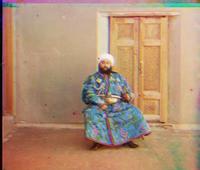
After about 10 lines of matlab code, I was able to produce the following composite:

Man, doesn't it take you back to the good ol' days of staring into those nutty images out of them 3D books with the cheapo 3D glasses? Awwwww.... Hours and hours of fun! ^^

Well, so the first obvious challenge here was to align the three images up so that they're correctly superimposed. The assignment suggested that we try a couple different metrics that, given two images, can give us an idea of how close thay match up. The first approach was to calculate the sum of squared differences or SSD. You might think it sounds fancy, but once you start taking the name literally, it becoms quite clear that it's dead simple. What you do is you take the differences in values at a given point on the two images, square it to get a positive value, then just add'em all up. If the number is low, that means there's not much difference between the two, and if the number is high, well... you get the idea.

The second method was to calculate the normalized cross-correlation value or NCC. As you may already know, when we talk about measuring the correlation between two given patterns (an image being just a pattern of color values), what we're trying to find out is how closely the two "co-vary". In other words, we're trying to find out how similar of a pattern the two are. This time, the higher the value, the more similar they would be.

So there you have'em, SSD and NCC. Now, how can we use these measurements to find out the correct way to superimpose the 3 images? Well, the simplest way would be to keep one image in place, superimpose another one, calculate either the NCC or the SSD value, slide it a lil bit, calculate the values again, etc... until you find yourself a decent SSD or NCC value that you're happy with. The amount by

which you had to move the second image before ending up at that value would be your choice of displacment for the image. This process is also known as convolution. So, what I did was I specified a 15x15 window of displacement that the second image could slide around in, and found the displacement that yielded the biggest NCC value. I did this for the blue and green channels pair and repeated it for the blue and red channels pair to align'em all up.

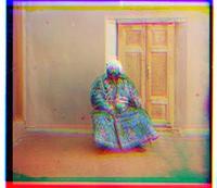
With this new feature implemented, the script shifted the green channel by 0, 6 and the red by 0, 13 before superimposing the two on top of the blue channel. The result seemed decent.

Now, do you notice how this image lacks the black border found in the original? Well, the clump of blackness messed up my calculations, so I chopped them off before aligning them up. The above photograph was particularly tricky because there were parts toward the bottom of one of the pictures that kept skewing the result. I could have probably spent more time finding a better area for comparison, or devised an automated approach such as edge detection to discard the portions of the channels where there would have been too strong of a match (i.e. clump of blackness compared to clump of blackness). Well, maybe, next time. ;)

So, is that it, you ask. Well, that woulda been suh-weeeeet, cuz at about this point I've had grown somewhat of an allergic reaction to matlab's quirky syntax. ;) So, no, it wasn't over, yet.

The second challenge came in the form of performance optimization. Calculating the SSD or NCC values over a 15x15 displacement window isn't horrible. Throw a P4 at it, and you'll get the images aligned in no time. Now, things get funky when we need to align images that are bigger, like... a lot bigger. The main issue would be

that we can no longer be content with a measley 15x15 displacement window, since, depending on how big the image is, we might have to bump that up to 100x100, or worse yet, 200x200 before finding a decent displacement amount!!! That would kinda suck... So we were given an algorithm that could potentially save us from having to spend days on end in the cluster: the Gaussian pyramid, aka the Burt-Adelson pyramid. If you're wondering why it is named after Gauss instead of the actual folks that first applied this idea to image processing, read this and you'll get to know why. =)

Anyway, the idea behind the Gaussian pyramid is that, instead of calculating the SSD or NCC values on the full image, we can calculate them on a scaled down version of the image. The image would obviously have to be small enough so that we can be happy with a measley 15x15 displacment window. When we get the SSD or NCC value on the scaled down image, we can first shift the image by that amount, scale the image back up a notch, rinse, lather repeat until we're back to our full resoltion image. So you see, the whole point is that since we're progressively shifting the image, the use of 15x15 displacment window can be good enough throughout the process, and oooooh yes, it runs much faster. ;)

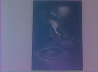
With all this done, I was curious to try and see if I can run my script through my very own RGB filtered photos. So I ripped some transparent filing labels off of my folders (yeah, I'm that cheap) and got down and dirty. ;) Here's what I ended up with

Here's the post-processed image:

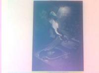
Now, it's pretty obvious the result sucks royal ass... Hmmph! I blame it on my sucky filters... =P In an attempt to try and see if I can make it any better, I implemented a simple white balancing script to get the following image:

Hmm... I suppose that's at least recognizable... ^^; Here is what it was supposed to look like:

So that's the end of the first assignment! If you're interested in taking a look at all the photographs that I have processed using my script, head over here. I just hope Prokundin-Gorksii can rest in peace now! :)

Light, Camera, Zoom!

posted by dJsLiM on Saturday, September 10, 2005 ::
click for class reference material ::

I'm picking up from the entry on the "Fundamentals of Photography", so be sure to start there if you have missed it! ;)

The first concept that I had trouble wrapping my head around was the concept of field of view. The term comes into play when we talk about the second most popular topic for stalkers and paparazzis: zooming. I'm guessing that the first would be infrared or x-ray photography for the hentai ojisans out there. =P At any rate, humor me while I try my best to explain the mechanics of zooming without getting confused all over again.

So, let's think for a moment about the effect we get when we press that trusty ol' zoom button on our cameras. What does it look like is happening? Well, to me it looks like the camera is basically taking a portion out of the center of the image and bringing it closer to me. *DUH*, you might say. Well, the subtle point I was trying to make by emphasizing the phrase "center of the image" was that zooming is NOT the same as taking a picture of the object when you're physically up close to it. The distinction arises from the fact that zooming

involves putting the lens, but not the screen on which the image gets projected on, closer to the object than it really is. In physics speak, what we're trying to do here is increase the focal length. So, why does increasing the focal length magnify the image, you ask. It's quite simple actually. To explain this phenomenon, we have to introduce that term I talked about at the top of this entry: field of view.

Field of view is the area which you're actually able get portrayed as an image in the viewfinder of your camera. In real life, the field of view defines what you can actually see with your eyes. For example, you can hopefully see what's directly in front of you, and if so, chances are good that you can also see things that are slightly off to the side, but you damn well can't see directly to the left or right unless you turn your head around. So the field of view is defined by the horizontal and vertical angles that you have visual access to.

So how are focal length and field of view related? Well, when you increase the focal length, the field of view shrinks. Think about it. The screen on which the image is projected on is of a finite size, and as you move the lens away from the screen to increase the focal length, the light rays will end up getting refracted by the lens sooner. This increases the distances traveled by the refracted rays before they hit the screen. As a result, the light rays will get projected further out on the screen, hence producing a magnified image. Now, as you zoom more and more, the rays that get refracted at higher angles will soon be out of reach by the fixed area of the screen. This leaves you

with only the rays that don't get refracted as much. So if you think about it, when you zoom, you're essentially bombarding most of your screen with rays of light that are exiting the lens at more or less parallel angles to the horizontal axis. In other words, you're throwing away much of the perspective information that would have normally been captured, so your image will no longer have much depth to it. That makes image captured through zooming, different from that captured up close.

Depthless or not, people can't seem to get enough this zooming business! Not only do we have cameras with optical and digital zoom features, you could literally buy lenses that let you zoom further and at higher qualities. They don't come cheap, and they're a pain in the ass to carry around, but they seem to sell pretty well. So something's gotta give, right? =P

There's also the subject of radial distortion, namely pin cushion and barrel distortions, that are often brought up while talking about the various phenomenon related to lenses. Well, unfortunately, the class never really dove into the details of what exactly causes these effects. The gist of it, however, is that the lens you have may be screwing your image up, but if you believe your bottle is half full, these distortions can become cool visual effects! I say either curse incessantly at your crappy lens or bask in glory as your friends drool at your artistically shape-shifted imagery. ;)

Phew! Allllllrighty! This completes the "Fundamentals of Photography" entry. Next time we'll talk about the color spectrum and the human eye! Stay tuned!

Fundamentals of Photography

posted by dJsLiM on Saturday, September 10, 2005 ::
click for class reference material ::

The classes are going pretty well, and many of the questions I've had about photography have been getting answered one by one. This is kinda cool given that I didn't even know that I was going to get an education on photography to begin with. ^^; The answers came in the form of physics lessons, and I have to say it's been ages since I had revisited optics. As a matter of fact, it almost feels as if this is the firs time I'm being exposed to these concepts. My guess is that my previous encounters with these subject matters were more mechanical in nature. In other words I was taught how to solve physic problems, not to truly understand what kind of a real world phenomenon was taking place. We need to reform our education system, dammit! Hmm... I suppose I could have been slacking and just didn't keep up with the work at that time, too... heh heh... Anyway... Lemme stop blabbering and get on with our first real topic of the blog: Fundamentals of photography.

The fundamental concept of photography on which all other facets are based on is the fact that a camera is basically a box that sits around collecting light rays that travel through a hole. Depending on the angle at which the light enters the hole, it'll meet with some plane behind the hole at a certain spot. The collection of light rays at these spots result in an image that we call a photograph. The physical hole through which light rays enter is called the

aperture, and the point at which the aperture resides is called the center of projection. If you put a screen behind the aperture, let light become projected on it, and measure the distance from the center of projection to the screen, you'd get what is known as the effective focal length of the camera. Now, if you were put a film in place of the screen, you'll be able to get yourself an imprint of the image projected on it. See, cameras aren't that complicated. ;)

An unfortunate characteristic of this imprint that a camera produces, however, is that it is incapable of accurately encoding the angle and the distance between and among the objects portrayed in the image. The reason is simple; the image is 2D and the real world is 3D. However, what's really interesting is that when we humans look at these images we're somehow able to make sense of it in our heads as to what thse objects really look like and how they would be positioned in real life! It turns out that our brain does a lot of these work for us to keep our sanity intact. Of course, the brain is only able to do this because it has been acquiring a lot of information through the eyes for a long time. It isn't without fault, however, as you can find instances where the information gathered can fool us into perceiving things incorrectly as well. The Muller-Lyer illusion, is a famouse illustration of such consequences.

So with the help of our brain, these flat images that we've managed to capture, turn out to be pretty neat things to have around. Given its usefulness, our forefathers probably thought this imaging device we call camera was worth spending some time to improve upon. One of the tricky design constraints that they noticed was that, the hole needed to be small enough to prevent too many rays originating from the same physical object from entering, yet large enough to let all the rays we want through. The problem with letting in too many rays of light reflected from the same physical object was that, the rays would enter the hole at different angles and scatter on to multiple

points on the screen, resulting in what we commonly refer to as a blur. So they managed to find a good size hole small enough to let the minimum number of rays in to produce a sharp image, but alas, with so little light passing through a hole of such small size, it was necessary for the photographer to stand around waiting for enough light rays to pass through the hole to produce a reasonably bright image.

This brings us to another important element of photography: exposure. Exposure is basically the time a photographer spends collecting light rays on the film or, if you're using a digital camera, a CCD or CMOS sensor array. Have you ever wondered why photographs taken at night on a digital camera without flash sometimes come out to be blurry? Well that's because the camera opted to use long exposure in order to collect as much light as possible, but since you couldn't keep your hands steady for that entire duration of the exposure, light rays got collected at multiple spots and produced a blurry image. Next time invest on a tripod, or keep a few tablets of diazepam handy. ;)

So to improve upon this pin-hole model, the next batch of innovators used a lens to grab rays of light that would have otherwise not passed through the hole, and directed them so that they would. This allowed the collection of more lights without long exposure.

Now, with the lens in our camera, we have a new measurement that we need to talk about; the focal length. The focal length of a lens is the distance from the optical center of a lens to the intersection point of all light rays that are parallel to the horizontal axis on which the lens stands once they get refracted. I know that sounds confusing, so take a look at these diagrams and see if they make more sense. Notice that this is different from the effective focal length previously discussed.

Unfotunately, plopping in a lens didn't only bring about a solution to our problem, but also presented some challenges. The artifact of having a lens was that, we now needed to care about focus. What the hell does that mean? Well, depending on the angle at which rays of light reflected from various physical objects got bent by the lens, they would end up converging on several different planes. It was no longer possible to just have the film residing on one plane recive equally focused rays of light to produce a sharp image of the entire captured scene. You may have lights converging to a single point behind where the film lies, which made the film collect the yet-to-be-focused rays of light and end up producing a blurry image of the object. So your entire image may not get blurred out, but objects located at different distances from the camera would end up with varying degrees of sharpness in the final photograph. There's even a cool term for the circular area of blurring you get when an object isn't focused! It's called circle of confusion. How cool is that?

The "simple" workaround for this problem is to shrink the aperture. The reason why this works requires us to think of the very reason why a blurry image gets produced in the first place; you're letting in more than one ray of light from the same physical object, and those extra rays are being projected onto multiple locations. So when you shrink the aperture, you're letting less of the rays in, and, as a result, decreasing the number of multiple projections that can even occur. But, this turns out to be kind of an ironic way of solving the problem, because it's going against the whole bloody reason we went with a lense in the first place: brightness. You see, when we have a smaller aperture, the amount of light that gets to pass through it, and, ultimately, the lens, is less than before, thus requiring more exposure to make up for it. Sounds like we're going around in circles, no? Well, the good news is that people have found aesthetical appeal in this artifact. They call it the use of the depth of field effect. Depth of field is the range at which the objects stay focused to

the naked eye. So when you talk about the effect of depth of field in your photograph, you're basically talking about selecting a set of objects that you'd like to keep in focus and another set of objects you'd like to have blurred. Hey, when the scientists are down and out, artists are always there to cheer'em up, I tell ya. ;)

Oook... So... This entry got super long... and I still have another topic to cover. Why don't I stop here, and talk about our next topic in a new entry? Alright? Stay tuned!

Ok, here we go

posted by dJsLiM on Friday, September 02, 2005 ::

So I'm taking another course at CMU this year. The course used to be called "Computer Graphics 2", but they're now calling it "Computational Photography" which, depending on your taste, makes it artsy and hip, fake and boring or somewhere in between. The content does seem to have become much more 2D image manipulation and extraction oriented, though. When I was in school, it used to be half 2D image stuff and half 3D (ya know, the usual sub-division surfaces and other crap) The shift sort of bummed me out because now the class uses Matlab as opposed to just hacking straight OpenGL. I guess from the point of view of the material, it makes more sense to concentrate on the algorithms rather than the hacking sensation you get out of OpenGL...

Well, regardless of the title of the course or the programming language used, I knew I wanted to take it before I took the next course on my list, so I didn't really care too much. Although... I really wanted to take the course when Professor Heckbert was teaching, but I have obviously missed that opportunity for good as all great Graphics professors continue to get snagged by korporate America. =( I'm sure Professor Efros will do fine, so I'm not too worried. =)

At any rate, the classes have begun this past Tuesday and the first assignment is out. I'm going to try and make this blog take the form of semi-stream of consciousness, in the sense that I'll put posts up talking mostly about me trying to make sense out of the material. Hopefully if other people take the course and go through similar struggles as I do, they'll reap some benefit out of it. Plus I find that it helps me really understand the material when I try to inform others of what I've learned. I don't claim that I'm right in everything I say here, so if you find me spewing a load of crap out of my trap, be sure to tell me to shove it (correcting me would be really cool, too)

Alright, let's get hacking, shall we?